Lutfi Al-Sharif, Ahmad M. Abu Alqumsan, Osama F. Abdel Aal
Mechatronics Engineering Department
University of Jordan, Amman 11942, Jordan
This paper was presented at The 2nd Symposium on Lift & Escalator Technology (CIBSE Lifts Group, The University of Northampton and LEIA) (2012). This web version © Peters Research Ltd 2019.
Keywords: Elevator, lift, round trip time, interval, up peak traffic, rule base, Monte Carlo simulation, average travel time, HARint plane.
Abstract: This paper presents a graphical methodology of visualizing the optimality of an elevator design solution. It introduces a new plane called the HARint plane, each point on which represents a solution to the elevator design problem.
By visually inspecting the plane and examining the intersection of various curves on the plane, the designer can understand how far the offered solution is from the optimal solution and also whether the offered design is wasteful.
The HARint plane comprises the quality of service, represented by the actual interval and the quantity of service, represented by the handling capacity. These are compared with the client/site requirements in terms of the target interval and the arrival rate. A number of curves can then be plotted on the plane based on the possible number of elevators and the car loading in passengers.
In drawing the curves on the plane, the round trip time has to be known. The round trip time can either be calculated analytically or by the use of Monte Carlo simulation. However, the calculation of the round trip time is only part of the design methodology. This paper does not discuss the round trip time calculation methodology as this has been addressed in detail elsewhere.
The optimality of the design is assessed by a clear step by step methodology that uses the user requirements to select an optimal design.
1. Introduction
The round trip time is the time needed by the elevator to complete a full journey in the building, taking passengers from the main entrance(s) and delivering them to their destinations and then expressing back to the main entrance, under up peak (incoming) traffic conditions.
This paper presents a step-by-step automated method for elevator design under specific arrival conditions, assuming that a method exists for calculating the round trip time. It uses a combination of rules and graphical methods to arrive at an optimal solution. A graphical tool, called the HARint plane, is presented as a means to visualise the solution.
The fact that the methodology is fully automated makes it very attractive for implementation as a software package. It has also been used for teaching elevator traffic analysis to final year undergraduate mechatronics engineering students.
Full details on the use of the method in optimising the number of elevators as well as the speed and capacity can be found in [1].
2. The problem with conventional design methods
It will be assumed that the designer starts with the knowledge of the following parameters that are given either by the architect or the building owner or that can be inferred from the type of occupancy (e.g., office, residential…etc.). These represent the user requirements.
a) The total building population, U. If this is not given directly, it can be calculated from either net floor area of the gross floor area.
b) The expected arrival rate, AR%. This is the percentage of the building population arriving in the building during the busiest five minutes. This value depends on the type of building occupancy.
c) The target interval inttar.
A sufficient design meets the following two conditions:
HC% ≥ AR% (1)
intact ≤ inttar (2)
…where:
AR% is the arrival rate expressed as a percentage of the building population in five minutes
HC% is the handling capacity expressed as a percentage of the building population in five minutes
inttar.is the target interval in seconds
intact.is the actual interval in seconds
A design that meets equations (1) and (2) is an acceptable design, but might not be an optimum design (i.e., it could be a wasteful design). The optimum design is one that meets the two equations shown below (3) and (4).
HC% = AR% (3)
intact = inttar (4)
In practice however, it is nearly impossible to find a design that meets both of equations (3) and (4) above. This is due the fact that the number of cars in the group, L, cannot be a fraction (it has to be a whole number). Hence, in practice, an optimum solution will satisfy the two equations (5) and (6) shown below:
HC% = AR% (5)
intact < inttar (6)
This section illustrates the main problem with the conventional design method. It relies on the user picking a suitable speed, v, and a suitable car capacity, CC. The user then assumes that the cars will fill up to the 80% of the car capacity.
The round trip time is then calculated based on the selected speed and the selected car capacity. This provides a value for the round trip time, τ . Dividing the round trip time by the target interval and rounding up the answer provides the required number elevators.
The user has now two values that represent the qualitative and quantitative performance of the systems: The handling capacity and the actual value of the interval, respectively. Comparing these values to the desired values, results in four possible cases, discussed in detail below.
| Quantitative Design Criterion |
Qualitative Design Criterion | |
| intact >inttar | intact < inttar | |
| HC% < AR% |
Case I |
Case II
|
| HC% > AR% |
Case III
|
Case IV Acceptable design, but might not be an optimum one. There may be further scope in reducing the number of elevators, reducing the rated speed or both. |
Specifically, there are two problems with this method:
- In the three cases where the design is unacceptable, the designer does not have a clear set of rules of how to move to an acceptable design (as defined in Case IV). It is a mixture of judgement, experience and trial and error.
- Even where the user manages to get to an acceptable design by arriving at Case IV, he/she cannot be sure that he/she has an optimum solution, despite the fact that the design meets both qualitative and quantitative criteria. The designer will have to do further trial and error iterations to check that the design is optimum (e.g., further reduce the number of elevators, L and then repeat the calculation of the round trip time). The main reason for this is that the designer starts from an arbitrary car size and assumes it fills up to 80% of its capacity rather than calculating the actual passenger arrival expected.
The next section attempts to address the drawback with this traditional methodology.
3. Analysis and development of the formulae
The design methodology developed in this section allows the designer to arrive directly at a design that is optimum and in a fixed number of steps without the need for trial and error searches or iterations. This section develops the method and the associated formulae.
Developing a clearly defined methodology for design with concrete steps, offers the following advantages:
- It allows designers to carry out the design regardless of their level of expertise, through a clearly defined set of rules.
- It offers the opportunity to automate the design process in software.
The methodology presented here uses the following rule:
The following parameters should be minimised in an optimal design in the following order of importance (that reflects the cost of the whole installation):
a) Number of elevators.
b) Elevator speed.
c) Elevator capacity.
So where two solutions have different number of elevators, the one with fewer elevators is selected; for solutions with the same number of elevators, the one with lower speed is selected; for solutions with same number of elevators and the same speed, the one with the smaller car capacity is selected.
Nevertheless, it is accepted that there are situations where the order of priority above is not correct (e.g., the restricted headroom in the building might restrict the rated elevator speed and force the designer to use a larger number of elevators in order to force a lower rated speed). In such conditions the designer can alter the rule for the priorities and select the answers accordingly.
The design process starts by finding the actual number of passengers that will board the elevator in any round trip journey. In effect, this is the number of passengers that will board the elevator from the main entrance (in the case of a single entrance arrangement) or the number of passengers boarding the car from all entrances (in the case of multiple contiguous entrances). This depends on three parameters that are all known at the start of the design process and are usually provided by the client, the developer or the architect. These are the target interval, tar int , the arrival rate, AR%, and the total building population, U. This is shown in equation (7) below.
The number of passengers arriving in the peak five minutes can be found by multiplying the arrival rate by the total population, as shown below (the five minute period has traditionally been used as the design basis in elevator systems):
P5min = AR%⋅U (7)
The arrival rate can then be expressed in units of persons per second by dividing by 300 seconds per minute as shown in (8) below.
 (8)
(8)
Thus an initial estimate of the actual number of passengers that will arrive in a single interval can be found by multiplying the target interval by the arrival rate of passengers as shown (9) below.
 (9)
(9)
The subscript i denotes the fact that is an initial estimate. It is worth noting that (9) is used in reference [4] as a tool to assess the actual interval at partial car loading, but not as a sizing tool.
There is no need at this stage to consider the car capacity. This can be done later when the final number of the passengers in the car has been determined.
Having arrived at an estimate for the actual number of passengers in the car, the next step is to find the corresponding round trip time. Using a classical method of calculating the round trip time [2] and [3] or using Monte Carlo Simulation [5], the value of the round trip time can be found.
The round trip time is in effect a function of the actual number of passengers if all other parameters are kept constant (such as the kinematics, number of floors, total building population, door timings, floor heights). This provides an initial value for the round trip time as shown in (10).
 (10)
(10)
From the calculated value of the round trip time, the required number of elevators can be calculated
 (11)
(11)
It is worth noting that this act of rounding up is unavoidable as a whole number of elevators can only be selected. The resultant number of elevators, L, is the nearest to the optimum as practically as possible.
Due to the process of rounding up to find the actual value of the interval will be slightly lower than the target interval, and the actual value of the handling capacity, HC%, will be slightly higher than the arrival rate, AR%.
The actual value of the interval can be found by dividing the round trip time by the number of elevators, as shown below in equation (12):
 (12)
(12)
The actual handling capacity can also be found by using equation (13) below:
 (13)
(13)
This provides an acceptable solution that satisfies Case IV discussed in the previous section. This is the optimum number of elevators required to meet the design criterion. However, it is not an optimum design regarding the required speed and car capacity. These two variables are discussed in detail in [1].
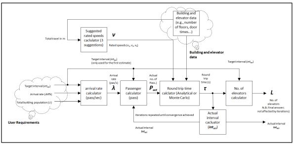
Figure 1: Block diagram showing the automated optimal design methodology.
Figure 1 shows an overview of the whole process of finding the optimum number of elevators, speed and capacity.
4. Graphical representation: The HARint Plane
The methodology described in the last section can be represented in a graphical format. The aim of the graphical representation in this case is to allow the designer to understand the effect of changes on the resulting solution, and be able to assess how far it is from the optimum solution.
In order to develop the graphical representation, a plane is presented. This plane has two axes; the x-axis represents the interval in seconds and the y-axis represents the handing capacity. Each point on the plane represents a possible solution (not necessarily an acceptable or correct one). The point representing the optimum solution, can be located by the intersection of the vertical line representing inttar and the horizontal line representing AR%, as shown in Figure 2. The plane is referred to as the HARint plane, as it contains the HC% and the AR% on the y-axis and the int on the x-axis (HCARint abbreviated to HARint).
Plotting lines of equal L (number of elevators) values and plotting lines of equal P (number of passengers) produces the HARint plane shown in Figure 2. The HARint plane can be very useful in visualising a specific solution and appreciating the optimality or otherwise of suggested solutions.
Figure 2 shows the position of the hypothetical optimum solution on the HARint plane which is the intersection point of the AR% horizontal line and the inttar vertical line. It is hypothetical because it is not achievable in practice as it requires a fractional number of elevators, L. Applying the rounding up equation (11) and then applying the iterations (as shown in reference [1]) moves the solution to the practical optimum solution (that lies on the AR% line and uses a whole number of elevators, L.
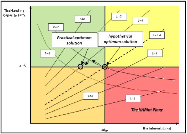
Figure 2: Hypothetical optimum solution and practical optimum solution on the HARint plane.
The use of the HARint plane shown in Figure 2 has been useful for visualising the solution, but has not been used to actually find a solution by the use of graphical methods. It might be possible to find a graphical method of finding a solution for a problem by the using the HARint plane as a solution chart (e.g., as the Smith chart is used in radio engineering and the Nichols chart is used in control systems). However, before this can be achieved, a method of normalisation needs to be introduced in order to make the HARint plane a universal tool.
5. Conclusions
A new methodology has been introduced that provides a set of rules and graphical methods that can be used to design elevator systems in buildings. The method optimises the number of elevators in the group of elevators for a building based on the user requirements of arrival rate (AR%), target interval (inttar) and the total building population (U). The methodology then optimizes the speed of the elevators and then the elevator car capacity. The method allows the user to work backwards from the actual arrival rate in the building in order to find the optimum number of elevators, instead of the trial and error method.
The methodology assumes that a method exists for accurately calculating the round trip time. Both analytical and Monte Carlo simulation methods can be used to calculate these parameters.
Due the automated and rule based nature of the methodology, it is very attractive for implementation in a software tool for the design of elevator systems.
The method has also been successfully used in teaching the principles of elevator traffic analysis to final undergraduate mechatronic engineering students at the University of Jordan. One of the main reasons for its success is that students do not possess any past experience in elevator traffic design and hence rely on the rule base and graphical methods in reaching an optimal and convergent design.
It is worth noting the analysis in this methodology has assumed a constant uniform passenger arrival process. Further work is currently being done in understanding the effect of a random arrival process on the results and the final answers.
REFERENCES
- Lutfi Al-Sharif, Ahmad M. Abu Alqumsan, Osama F. Abdel Aal, “Automated optimal design methodology of elevator systems using rules and graphical methods (the HARint plane)”, Building Services Engineering Research and Technology, published online before print 12th April 2012, doi: 10.1177/0143624412441615.
- CIBSE, “CIBSE Guide D: Transportation systems in buildings”, published by the Chartered Institute of Building Services Engineers, Third Edition, 2005.
- G.C. Barney, “Elevator Traffic Handbook: Theory and Practice”, Taylor & Francis, 2002.
- G. C. Barney, “Traffic Design” in Elevator Technology, Ellis Harwood, 1986.
- Lutfi Al-Sharif, Husam M. Aldahiyat, Laith M. Alkurdi, “The Use of Monte Carlo Simulation in Evaluating the Elevator Round Trip Time under Up-peak Traffic Conditions and Conventional Group Control”, Building Services Engineering Research & Technology, Sage Publications, August 2012 33: 319-338,