Lutfi Al-Sharif , Enas AlOsta, Noor Abualhomos, Yazan Suhweil
Mechatronics Engineering Department, School of Engineering
The University of Jordan, Amman 11942, Jordan
This paper was presented at The 7th Symposium on Lift & Escalator Technology (CIBSE Lifts Group and The University of Northampton) (2017). This web version © Peters Research Ltd 2019.
Keywords: Elevator, lift, high rise buildings, double deck elevator, round trip time, up-peak traffic, incoming traffic, Monte Carlo Simulation.
Abstract. One of the sources of efficiency in the operation of double deck elevators is the simultaneous transfer of passengers into and out of the elevator cars, thus leading to a reduction in the value of the round trip time, and thus an increase in the handling capacity.
However, due to the randomness of passenger destination selections, this reduction is not optimal. This paper presents this phenomenon as an efficiency coefficient, denoted as the Passenger Transfer Efficiency Coefficient (PTEC) and is representative of the time taken by passenger to alight from the double deck elevator.
PTEC is mainly applicable to passengers alighting, rather than passengers boarding. This is true in the case of a single pair of entrances. For the case of multiple pairs of entrances, the PTEC applies to both alighting and boarding operations.
A set of equations are derived in order to calculate the PTEC. The results from the equations are verified using the Monte Carlo simulation method. The method of stepwise verification has been used in order to verify the equations.
Nomenclature
L the number of elevators in the group
N the total number of floors above the pair of main entrances
P the number of passengers per deck
Pe the number of passengers for the even deck
Po the number of passengers for the odd deck
PTEC passenger transfer efficiency coefficient
S is the expected value of the number of stops in a round trip
tp the passenger alighting or boarding time in seconds
U is the total building population in persons
Ui is the population of the ith floor in persons
Ue is the total population of the even floors in persons
Uo is the total population of the odd floors in persons
1 Introduction
Double deck elevators offer a very efficient means of moving people within buildings ([1], [2] and [3]). By placing two conventional single deck elevators one on top of the other and attaching them rigidly, shaft space is saved. Passengers board both decks at the same time, whereby passengers heading to an odd floor board the lower deck and passenger heading to the even floors board the upper deck. The elevator then moves two floors at a time. Once a stop is made, passengers alight simultaneously from the upper and lower decks to the even and odd destination floors respectively.
There are three sources of efficiency that arise from using double deck elevators:
- The effective number of stops is reduced due to the fact that the potential number of floors is halved (N/2 instead of N). This reduces the value of the round trip time and thus increases the handling capacity.
- The passenger boarding and alighting time is reduced due to simultaneous boarding and alighting of passengers on the two decks.
- Due to the fact that the two elevator cars are mounted on top of each other, the car capacity is increased without a major increase in the core space usage.
Double deck elevators are mainly used in two broad applications ([4], [5]):
- They are effective as shuttles between the ground floor and sky lobbies. The efficiency arises from the fact that there are only two stops (or three stops) thus reducing the value of the round trip time. The elevator car capacity in such situations is made relatively large.
- They are currently increasingly being used in low and medium rise buildings in cases where the floor populations are relatively high. For example, double deck elevators can be very effective in buildings with more than 250 persons per floor (examples are given in [6]).
Barney [4] presents a comprehensive list of the double decker installation around the world and their applications. Siikonen [7] presents the equations for the expected number of stops (S) and the highest reversal floor (H) for the case of equal and unequal populations and derives a parameter for the passenger transfer efficiency. Genetic algorithms have been widely applied in elevator traffic control systems examples of which can be found in ([7], [9], [10] and [11]). More specifically, Sorsa et al. [8] use genetic algorithms to achieve optimal control of double deck elevators.
Two pieces of work on double deck elevator formulae are given by Kavounas [12] and Peters [13] and [14]. Kavounas derives a formula for the highest reversal floor and the expected number of stops. Peters [13] and [14] presents formulae for the general case under Poisson arrival conditions. However, it is difficult to carry out comparison with the results in these papers as they do not present any closed form equations (instead, calculations that they present are iterative and require computer implementation).
The published research in the area of double deck elevator does not address the following two points:
- No mathematical formula has been derived for the passenger transfer efficiency (i.e., the quantification of the benefits of simultaneous passenger alighting at the destination floors). The main aim of this paper is to derive a formula for the passenger transfer efficiency. This is critical in enabling the correct calculation of the round trip time ([15], [16], [17]).
- No verification has been carried out to ensure the accuracy of the derived equations. The derived equations presented in this paper have been verified using the Monte Carlo Simulation method (MCS).
Section 2 introduces some necessary assumptions and numbering conventions used in this paper. Section 3 introduces the concept of the passenger transfer efficiency and derives equations for the PTEC for the cases of equal floor populations. Section 4 discusses a similar parameter presented by Siikonen. Section 5 presents a numerical example to understand the effect of the number of passengers, P, and the number of floors, N, on the coefficient. Conclusions are drawn in section 6.
2 Assumptions and numbering conventions
In this section some of the assumptions are clearly stated as well as the numbering notation for the building. It is necessary to clearly state some of the assumptions that will be made within this paper and provide some background required for the derivations.
Throughout this paper, it will be assumed that a single pair of entrances is used for boarding. There is only one pair of entrance floor, which is in effect a single entrance scenario. Each passenger can only enter the building through one floor: the odd entrance for odd destination occupant floors and the even entrance for even destination occupant floors.
It will also be assumed that all traffic is incoming traffic. Incoming traffic is traffic that originates at an entrance floor and terminates at an occupant floor. This is not an unreasonable assumption to make. The reason for this is that double deck elevators are usually operated in double deck mode under incoming traffic conditions during which they are most efficient. The design of double deck elevators is still based on the morning incoming traffic (up peak traffic). It is usual to operated double deck elevators in single deck mode outside peak hours. Under single deck mode, one of the decks is deactivated and the other deck serves passengers as a single deck.
It is also necessary to define the concept of a twin pair of floors, one of which is odd and the other even. This concept is critical to all the derivations that will follow in this paper. A twin pair of floors is, as the name implies, consecutive floors at which the double deck will make a simultaneous stop and deliver passengers. For brevity in the analysis below, the pair of twin floors will be simply referred to as twin floors. The lower floor will be assumed to be the odd floor and given the subscript o for odd; the upper floor will be assumed to be the even floor and given the subscript e for even. A general overview of the arrangement of a building that is served by double deck elevators is shown in Figure 1.
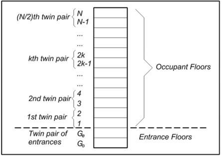
Figure 1: General overview of a building served by double deck elevators, showing the numbering convention used.
It will also be assumed that the number of occupant floors is even. This is the most efficient arrangement. However, some notes are given in [18] as to how the case of an odd number of occupant floors can be addressed.
3 Derivation of the formula for the Passenger Transfer efficiency coefficient
The passenger transfer efficiency coefficient (PTEC) is unique to double deck elevator systems (or to multiple deck systems in general). It is a measure of the efficiency of the passenger transfer time (i.e., boarding and alighting). There are two phases of passenger transfer in any elevator: boarding time and alighting time.
Based on a single pair of entrances, passenger transfer efficiency during boarding is not a concern (noting that it is assumed that all the traffic is incoming only). It is assumed that all P passengers for each deck (i.e., the upper deck and the lower deck) start boarding at the same time and finish boarding at the same time. Thus there is no wasted time and full efficiency is automatically attained.
However, the issue of passenger transfer efficiency is more of a concern during alighting. As there are many occupant pairs of floors (that will act as destinations for passengers) it is likely that different numbers of passengers are destined for the odd and even floors of the same stop. The most efficient scenario would take place in a double deck elevator when an equal number of passengers from the two decks alight at the same stop. In this case it can be stated that there is no wasted time, as there is no wasted waiting time at one deck while one or more passengers are alighting from the other deck.
For example, if at one of the double decker stops, five passengers alight from the upper (even) deck and one passenger alights from the lower (odd) deck, then the actual alighting time is equal to the time required for the five passenger to alight from the upper deck. The difference between the numbers of passengers intending to alight at this stop has effectively caused a loss of time. Had the number of passengers intending to alight been equal (i.e., three passengers for the upper deck and the three passengers for the lower deck) then the total alighting time would have been only equal to the time required for three passengers to alight, resulting in a saving equal to the time required by two passengers to alight. It is this efficiency (or inefficiency) that this parameters aims to capture. The formula for the case of equal floor population will be derived in this section.
In order to derive a formula for the PTEC, it is necessary to find an expression for the probability of the number passengers destined for the odd floor of the twin pair of floors being equal to i and the passengers destined for the even floor of the twin pair of floors being equal to j.
Each of these events shall be denoted as A and B respectively, as follow:
A is the event under which i passengers are destined for the odd floor of the pair of twin floors.
B is the event under which j passengers are destined for the even floor of the pair of twin floors.
For each of these events, the probability distribution function is effectively a binomial distribution (i.e., a passenger can either head or not to a certain floor). For each deck, it is assumed that P passengers will board the deck in each round trip at the main entrance.
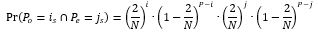
It is now necessary to find the probability of i specific passengers going to a floor. This implies that other P-i passenger did not go to that floor. The probability of the joint event is the product of the two probabilities:
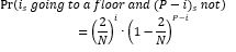 (1)
(1)
This can then be applied to the odd floor of the twin floors and the even floor of the twin floors as shown in the two equations below. (It is implied that if i specific passengers go the floor then P-i passengers will not without the need to explicitly state it in the formula).
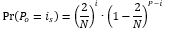 (2)
(2)
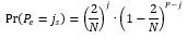 (3)
(3)
As the two events are independent, then the combined event whereby i specific passengers head to the odd floor and j specific passengers head to the even floor of the twin pair of floors is:
 (4)
(4)
In the terminology used in the derivations so far the term specific passengers has been used. This emphasises the fact that the derivation involves a specified set of i passengers and a specific set of j passengers. But the event will take place if any combination of i passengers in the odd deck are destined for the odd twin floor and if any combination of j passengers in the even deck are destined for its twin even floor. There are a number of different ways in which i passengers can be picked out of a total of P passengers and a number of different ways in which j passengers can be picked out of P passengers in even deck. These are in effect combinations and standard formula for combinations can be used as shown in the equation below.
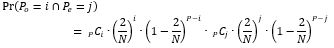 (5)
(5)
This equation is now used to populate a dedicated matrix as shown below. The row index represents number of passengers heading to the odd floor of the twin pair of floors and the column index represents the number of passengers heading to the even floor of the twin pair of floors. The matrix is a P+1 by P+1 square matrix, as it is important to include the possible case whereby there are no passengers alighting from either deck.
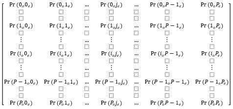
Where: Pr(io je) is the probability that i passengers go to the odd floor and j passengers go to the even floor.
It is worth noting the following points about the different areas of this matrix:
1. The diagonal elements of the matrix represent the cases where the numbers of passengers destined for each of the odd and even floors of the twin are equal. For example, Pr(3o3e) is the probability of three passengers being destined to the odd floor of the twin pair of floors and the three passengers destined to the even floor of the same twin pair of floors.
Pe = Po
In this case, the actual passenger transfer time is the time required for either deck as they are equal (i or j). This is the most efficient case as there is no loss of efficiency in passenger transfer.
2. The upper triangle of the matrix (i.e., above the diagonal as shown in the figure below) represents the cases where the number of passengers destined for the even twin floor is larger than the number of passengers destined to the odd floor of the twin pair of floors. In other words:
Pe > Po
In this case, the actual passenger transfer time is the time required for the even deck passengers to alight, which is the column index, j. In this case, there is a loss of efficiency in passenger transfer, proportional to the difference between i and j.
3. The lower triangle of the matrix (i.e., below the diagonal) represents the cases where the number of passengers destined to the odd twin floor is larger than the number of passengers destined to the even twin floor. In other words:
Po > Pe
In this case, the actual passenger transfer time is the time required for the odd deck passengers to alight, which is the row index, i. In this case as well, there is a loss of efficiency in passenger transfer, proportional to the difference between i and j.
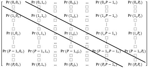
The next step is to find the expected maximum number of passengers alighting. Use will be made of the three areas of the matrix: one equation will be developed for the upper triangle of the matrix, one for the diagonal of the matrix and one for the lower triangle of the matrix.
The expected value of the maximum number of passengers alighting at each stop for the even number of passenger can be found by summing the product of the probability of each number of passengers alighting by their number from the upper triangle of the matrix. The limits of the summations ensure that the number of passengers alighting on the upper (even) deck is larger than the passengers alighting from the lower (odd deck).
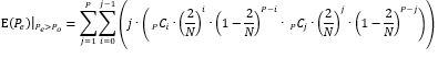 (6)
(6)
The same is repeated for the lower triangle of the matrix as shown in the equation below.
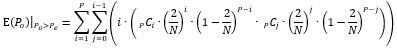 (7)
(7)
Equations (6) and (7) contain two terms: one involves the number of passengers alighting at the even floor and the other the number of passengers alighting at the odd floor.
As for the diagonal terms, there is only one summation and the index runs from 1 to P (the case where both Pe and Po are zero is disallowed, as there would not be a stop in the first place if there are no passengers heading to either floor of the twin).
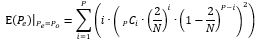 (8)
(8)
Combining all the three cases, it is possible to evaluate the expected value of the maximum number of passengers alighting per twin pair of floors. The expected value is the summation of the three contributions to the expected value in the three cases.
 (9)
(9)
However, there are N/2 twin number of floors, where N is the total number of floors above the main entrance. Thus the expected value of the maximum number of passengers alighting in a round trip is:
 (10)
(10)
Finally, the PTEC is the ratio between the expected value of the maximum number of passengers alighting in each round trip divided by the number of passengers per deck.
 (11)
(11)
The equations derived above for the value of PTEC have been rigorously verified using the Monte Carlo simulation method ([19], [20], [21]) with excellent agreement. More details of numerical examples can be found in [18].
It is expected that the value of the PTEC will improve (i.e., become smaller and more efficient) under destination group control ([22], [23], [24], [25], [26], [27]). This is the current of future research whereby the formula is re-derived under destination group control conditions.
4 The Coefficient Presented by Siikonen
Siikonen derived a coefficient for passenger transfer loading [7]. The derivation will be presented below:
The probable number of stops equals to:
 (12)
(12)
Where P2k,d is the probability of passenger going to 2k-1 or 2k floor.
 (13)
(13)
The probable number of stops for upper deck only equals to:
 (14)
(14)
Where P2j,s is the probability of passenger going to even floor.
 (15)
(15)
Then, the total passenger transfer time will equal:
 (16)
(16)
This equation assumes that inefficiencies will occur in both alighting and boarding, whereas in this paper the authors have assumed that inefficiency only takes place in alighting and not in boarding. Siikonen also assumes that the population of every twin pair of floor is equal (i.e., the population of the even floor of the twin pair is equal to the population of the odd twin pair) so that the numbers of stop for single deck for odd and even are equal.
5 Numerical Example
In order to gain a numerical appreciation of the range of values of the coefficient (i.e., the PTEC), a numerical example is presented in this section for a realistic range of values for P and N. As discussed earlier in this paper, the coefficient will range from the smallest possible value of 1 (representing full efficiency in passenger alighting from both decks) to the maximum possible value of 2 (representing zero efficiency in passenger alighting from both decks).
Assuming a building with equal floor populations and equal capacity for both decks and an even number of floors above the pair of main entrances, the PTEC was calculated for a range of value of P and N. The results are shown in Table 1.
Table 1: The value of the PTEC for a number of buildings.
| N (number of floors above the main entrance) | ||||||
| P (each deck) | 10 | 12 | 14 | 16 | 18 | 20 |
| 10 | 1.3474 | 1.3848 | 1.4187 | 1.4485 | 1.4763 | 1.5012 |
| 13 | 1.3062 | 1.3411 | 1.3713 | 1.3992 | 1.4243 | 1.4474 |
| 17 | 1.2699 | 1.3001 | 1.3274 | 1.3521 | 1.375 | 1.3958 |
| 20 | 1.2486 | 1.278 | 1.3029 | 1.3262 | 1.3475 | 1.3679 |
| 26 | 1.2186 | 1.2445 | 1.2666 | 1.2875 | 1.3069 | 1.3247 |
As can be seen from the results, the value of the PTEC ranges from around 1.2 up to 1.5. As the number of passengers per deck increases, the efficiency increases (with smaller value of PTEC) as expected. Moreover, as the number of floors above the main entrances increases, the efficiency decreases (with a larger value of PTEC) as expected.
Conclusions
A new parameter has been introduced that measures the efficiency of the passenger transfer time denoted as the PTEC (passenger transfer efficiency coefficient). It represents how efficient the transfer of passenger is when alighting at the destination floors. The PTEC can be used in the calculation of the round trip time whereby it provides an accurate measure of the passenger transfer time. The PTEC has been derived for the case of equal floor populations. The derived equations have been verified using the Monte Carlo Simulation method with excellent agreement. A similar coefficient presented by Siikonen is also studied. A numerical example is given for a number of buildings in order to show the effect of the number of passengers per deck (P) and the number of floors above the pair of main entrances (N) on the value of the coefficient. It is shown that the value of the coefficient increases with the increase in N and decreases with the increase in P.
REFERENCES
- Fortune J. Modern Double Deck Elevator Applications and Theory. Elevator Technology 6 1995; 6: 230-238. Proceedings of the 6th International Conference on Elevator Technologies, Elevcon ’95, Hong Kong March 1995. Published by the International Association of Elevator Engineers.
- CIBSE. CIBSE Guide D: Transportation systems in buildings. Published by the Chartered Institute of Building Services Engineers, Fifth Edition, 2015.
- Barney G C and Al-Sharif L. Elevator Traffic Handbook: Theory and Practice. 2nd Edition. Routledge. 2016.
- Barney G C. Vertical Transportation in Tall Buildings. Elevator World 2003; 51(5): 66-71.
- Binder G. One Hundred and One of the World’s Tallest Buildings. The Images Publishing Group, Victoria, Australia, 2006.
- Al-Sharif L and Seeley C. The effect of the building population and the number of floors on the vertical transportation design of low and medium rise buildings. Building Services Engineering Research and Technology 2010; 31(3): 207-220. doi: 10.1177/0143624410364075. August 2010.
- Siikonen M L. On Traffic Planning Methodology. Elevator Technology 10 2000; 10: 267-274. Proceedings of the 10th International Congress on Elevator Technologies, Berlin Germany May 2000. Published by the International Association of Elevator Engineers.
- Sorsa J, Siikonen M L and Ehtamo H. Optimal control of double-deck elevator group using genetic algorithm. International Transactions in Operational Research 2003; 10: 103-114.
- Tapio Tyni, Jari Yilnen, “Genetic Procedure for Allocating Landing Calls in an Elevator Group”, 25th May 1999, US Patent number: 5907137.
- T. Eguchi, K. Hirasawa, J. Hu, S. Markon, “Elevator group supervisory control systems using genetic network programming”, Congress on Evolutionary Computation, 2004, IEEE, 19th to 23rd June 2004, pp 1661-1667 (volume 2).
- P. Cortes, J. Larraneta, L. Onieva, “Genetic algorithm for controllers in elevator groups: Analysis and simulation during lunch-peak traffic”, Applied Soft Computing, Volume 4, Issue 2, May 2004, Pages 159–174.
- Kavounas G. Elevatoring Analysis with Double Deck Elevators. Elevator World 1989; 37(11): 65-72.
- Peters R D. Lift traffic analysis: General formulae for double deck lifts. Building Services Engineering Research and Technology 1996; 17(4): 209-213.
- Peters R D. General Analysis Double Decker Lift Calculations. Elevator Technology 6 1995; 6: 165-174. Proceedings of the 6 International Conference on Elevator Technologies, Elevcon ’95, Hong Kong March 1995. Published by the International Association of Elevator Engineers.
- Al-Sharif L. Calculating the Elevator Round Trip Time for the Most Basic of Cases (METE II). Lift Report 2014; 40(5): 18-30. Sep/Oct 2014.
- Al-Sharif L, Abu Alqumsan A M and Khaleel R. Derivation of a Universal Elevator Round Trip Time Formula under Incoming Traffic with Stepwise Verification. Building Services Engineering Research and Technology 2014; 35(2): 198–213. doi 0143624413481685.
- Al-Sharif L and Abu Alqumsan A M. Stepwise derivation and verification of a universal elevator round trip time formula for general traffic conditions. Building Services Engineering Research and Technology 2015; 36(3): 311-330. doi: 10.1177/0143624414542111.
- Al-Sharif L, AlOsta E, Abualhomos N and Suhweil Y. Derivation and Verification of the Round Trip Time Equation and Two Performance Coefficients for Double Deck Elevators under Incoming Traffic Conditions. Building Services Engineering Research and Technology 2017; 38(2): 176-196.
- Powell B. The role of computer simulation in the development of a new elevator product. Proceedings of the 1984 Winter Simulation Conference, page 445-450, November 1984, Dallas, TX, USA, published by INFORMS, Catonsville, MD 21228, United States.
- Tam C M and Chan A P C. Determining free elevator parking policy using Monte Carlo simulation. International Journal of Elevator Engineering 1996; 1:24-34.
- Al-Sharif L, Aldahiyat H M and Alkurdi L M. The use of Monte Carlo simulation in evaluating the elevator round trip time under up-peak traffic conditions and conventional group control. Building Services Engineering Research and Technology 2012; 33(3): 319–338. doi:10.1177/0143624411414837.
- Peters R. Understanding the benefits and limitations of destination dispatch. Elevator Technology 16, The International Association of Elevator Engineers, the proceedings of Elevcon 2006, June 2006, Helsinki, Finland, pp 258-269.
- Smith R and Peters R. ETD algorithm with destination dispatch and booster options. Elevator Technology 12 2002; 12: 247-257. The International Association of Elevator Engineers (Brussels, Belgium), proceedings of Elevcon 2002, Milan, Italy, June 2002.
- Joris Schroeder, “Elevatoring calculation, probable stops and reversal floor, “M10” destination halls calls + instant call assignments”, in Elevator Technology 3, Proceedings of Elevcon ’90, International Association of Elevator Engineers, 1990, pp 199-204.
- Sorsa J, Hakonen H and Siikonen M L. Elevator selection with destination control system. Elevator Technology 15 2005; volume 15. The International Association of Elevator Engineers (Brussels, Belgium), proceedings of Elevcon 7th to 9th June 2005, Peking, China.
- Lauener J. Traffic performance of elevators with destination control. Elevator World (Mobile, AL, USA) 2007; 55(9): 86-94.
- Al-Sharif L, Hamdan J, Hussein M, Jaber Z, Malak M, Riyal A, AlShawabkeh M and Tuffaha D. Establishing the Upper Performance Limit of Destination Elevator Group Control Using Idealised Optimal Benchmarks. Building Services Engineering Research and Technology, 2015; 36(5):546-566. September 2015.
BIOGRAPHICAL DETAILS
Lutfi Al-Sharif is currently professor of building transportation systems at the Mechatronics Engineering Department at the University of Jordan, Amman, Jordan. His research interests include elevator traffic analysis and design, elevator and escalator energy modeling and simulation and engineering education.
Enas AlOsta, Noor Abualhomos and Yazan Suhweil all graduated from the department of mechatronics engineering at the University of Jordan, Amman, Jordan in 2017.